R800 User’s Manual
Preliminary version
ASCII corporation
Systems division
1991-01-24
Source images posted here and here by Japanese MSX user Kinnoji.
1 Features
- A 16-bit ALU pass is adopted to speed up the arithmetic processing.
- Execute 16-bit arithmetic operation in one system clock.
- Supports 24-bit wide address space.
- Built-in memory mapper of 9 entries and memory expansion is possible with 16 MB.
- The built-in DRAM interface allows direct connection of DRAM.
- Direct connection of DRAM is possible.
- Built-in refresh controller (refresh is CAS before RAS method).
- Supports DRAM high-speed interface (page mode), so it can be accessed by computer.
- Built-in clock generator (28 MHz).
- Enhanced interrupt functionality.
- Indirect addressing interrupt with 7 levels of priority.
- Built-in 2 channels of DMA controller.
- CPU clock is about 7 MHz and most 1 byte instructions can be executed in 1 CPU clock.
- Compatible with Zilog Z80 and instruction code upper.
- All Z80 instructions are supported.
- Supports 8-bit instructions in IX and IY registers.
- Supports multiplication instructions.
- FAST mode (performs block transfer of IO data in one instruction fetch).
- Bidirectional mapper address pin.
- When the path is open, access can be made from the DRAM section by inputting all addresses and /ERAS from the outside.
7 Internal Extension Register
R800 has registers for interrupts, DMA, and memory mapper. Register bit assignments are shown below. The internal IO registers are accessed by bringing the /CSREG pin low. When the address signal A0 is “Low”, the pointer of the internal IO register is latched, and when it is “High”, the data is written. The pointer is auto-incremented at each data write, so high-speed data transfer to the memory mapper registers etc. is possible.
Internal register pointer register (/CSREG=L, A0=L, R/W)
 B7   B6   B5   B4   B3   B2   B1   B0
  -  IRA6 IRA5 IRA4 IRA3 IRA2 IRA1 IRA0
IRA: Internal Register Address
Internal register write / read data register (/CSREG=L, A0=H)
 B7   B6   B5   B4   B3   B2   B1   B0
DAT7 DAT6 DAT5 DAT4 DAT3 DAT2 DAT1 DAT0
8 Interrupt Operation
The R800 interrupts have the following 4 modes.
10 DMA Controller
In R800, the DMA controller has 2 channels of DMA0 and DMA1 built-in, and DMA0 loses its priority first. The transfer destination address and transfer source address can be set to 24 bits each and the transfer byte count can be set to 16 bits. There is no 64K byte boundary for the transmission byte count because a 24-bit counter is used.
It has a transfer source start address setting register (24 bits), transfer destination start address setting register (24 bits), transfer number setting register (16 bits) and mode register (8 bits) for each of the 2 channels of the DMA controller. Refer to the internal extension register section for details on register writing.
Transfer source start address setting register. (Write only)
Lower address setting register
 B7   B6   B5   B4   B3   B2   B1   B0
 A7   A6   A5   A4   A3   A2   A1   A0
Internal register address
Channel 0: 20H
Channel 1: 30H
Middle address setting register
 B7   B6   B5   B4   B3   B2   B1   B0
MA15 MA14 MA13  A12  A11  A10  A9   A8
Internal register address
Channel 0: 21H
Channel 1: 31H
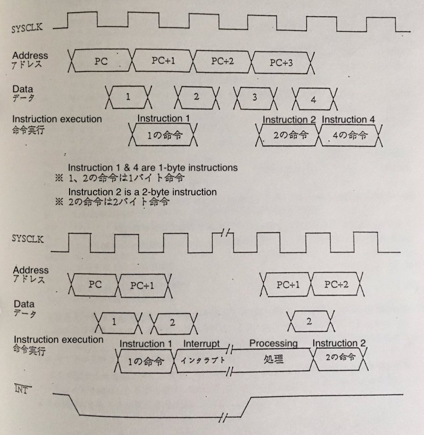
15 Instruction Execution
The R800 executes an instruction in SYSCLK units obtained by dividing the XTAL frequency by 1/4. Also, since instruction fetching and instruction execution are pipelined, the next instruction fetch is performed during instruction execution. (See figure below.) If the prefetched instruction can not be executed due to an interrupt or bus request, etc., the instruction that could not be executed will be fetched again after the service such as interrupt or bus request is finished.